EMC measurement is how a lab records the unwanted radio-frequency energy your product gives off, using defined instruments and a defined setup. Knowing the method tells you whether to trust a pass or a fail.
This guide covers emissions. It explains conducted and radiated tests, the equipment between your product and the display, the frequency bands, and how to read the report you receive. Limits are not covered, because they belong to the product standard.
If you are new to the field, start with the basics of EMC.
What does an EMC emissions measurement actually measure?
The EMC Directive states the goal in general terms. Equipment must not generate disturbance above a level that stops radio, telecommunication and other equipment from operating as intended [1].
A standard turns that goal into numbers. Equipment that conforms to a harmonised standard, whose reference is published in the Official Journal, is presumed to meet the essential requirements that standard covers [1].
For multimedia equipment, the consolidated harmonised list names EN 55032:2015 together with its A11:2020 amendment [2]. CISPR 32 is the international text behind it, with scope for equipment up to 600 V supply, Class A and Class B [3].
The presumption of conformity attaches to the reference on the Commission’s list, EN 55032:2015 with A11:2020 [2].
The measurement rules quoted later in this guide come from the international text CISPR 32:2015/AMD1:2019. Confirm the current EN amendment on the CENELEC record before you rely on presumption [3][4].
The product standard owns the limits. The measurement rules sit in separate “basic” standards. These give measurement techniques and contain no prescribed limits, while product standards add limits and point to the basic ones for test procedures [12].
For emissions, the basic standards are the CISPR 16 series. CISPR 32 itself points to part 16-4-2 for uncertainty [3], and the wider series defines the apparatus and methods behind the test [12].à’
The Table
The table below shows which part answers which question. It is orientation only. Buy the parts you need from the official store, and read the edition and amendments your own product standard cites.
| CISPR 16 part | Question it answers | Edition and amendments |
|---|---|---|
| 16-1-1 | What must the receiver or analyser do? | Edition 5.0 (2019) [5] |
| 16-1-2 | What must the LISN, probes and other coupling devices do? | Edition 2.1, 2014 with AMD1:2017, consolidated [6] |
| 16-1-4 | What must antennas and test sites do? | Edition 5.0 (2025) [7] |
| 16-2-1 | How is a conducted measurement made? | Edition 3.0, 2014 with AMD1:2017, consolidated [9] |
| 16-2-3 | How is a radiated measurement made? | Edition 4.0, 2016 with AMD1:2019 and AMD2:2023 [10] |
| 16-4-2 | How is instrument uncertainty handled? | Edition 2.2, 2011 with AMD1:2014 and AMD2:2018, consolidated [11] |
Editions move. Part 16-1-4 was replaced by a fifth edition in 2025, taking over from the fourth edition and its two amendments [7]. Check which edition your product standard and your lab’s report actually cite.
What is the difference between conducted and radiated emissions?
Conducted emissions travel along cables. The lab measures them as a voltage or current on the power and signal lines. CISPR 16-2-1 covers these methods, with the main focus on 9 kHz to 30 MHz [9].
Radiated emissions leave through the air, from the enclosure and from cables that behave like antennas. The lab measures them as field strength. CISPR 16-2-3 covers these methods from 9 kHz to 18 GHz [10].
Below 30 MHz, a loop antenna usually measures the magnetic field, and a monopole, which is an electric-field antenna, is also used. Above 30 MHz, the lab uses electric-field antennas such as biconical and log-periodic types [14].
The split tells you where to look when a result fails. Conducted failures usually point to filtering and layout where the cable enters the product. Radiated failures usually point to cable shielding, common-mode currents and enclosure seams.
For the conducted side, the filter design guide shows what to change once you know the problem.
What equipment sits between the product and the receiver?
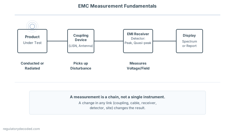
A measurement is a chain, not a single instrument. The product feeds a coupling device, a cable carries the signal, and a receiver or analyser displays the result. Each link adds its own error.
Several practical points below come from a receiver manufacturer’s technical note on CISPR 16-1-1, not the standard itself [14].
EMI receiver or spectrum analyser?
CISPR 16-1-1 sets requirements for measuring equipment from 9 kHz to 18 GHz, and it applies to both EMI receivers and spectrum analysers [5]. The label matters less than what happens ahead of the first mixer.
Most disturbance signals are pulse-like and broadband [14]. An EMI receiver has preselection filters that reject most of that energy before the first mixer. A spectrum analyser has none, so its first mixer sees the whole spectrum and can overload [14].
An overloaded mixer produces readings that look plausible and are wrong. That is why a pre-compliance analyser is good for finding problems but needs care before anyone trusts the number.
Which coupling devices does a lab use?
The receiver never touches your product directly. A coupling device picks up the disturbance first, and CISPR 16-1-2 defines the conducted ones [6]. The common devices are:
- LISN, also called AMN. A line impedance stabilisation network. The common V-type measures the unsymmetrical voltage on mains lines, usually up to 30 MHz [14].
- T-LISN or ISN. Measures the asymmetrical voltage on balanced data lines [14].
- Voltage probe. Used where a LISN cannot be, for example because of very high currents [14].
- Absorbing clamp. Measures disturbance power on power cords from 30 MHz to 1 GHz [14].
- Antennas. Loop antennas below 30 MHz. Biconical, log-periodic dipole array and horn antennas above 30 MHz [14].
A LISN gives the product a defined impedance to work into and passes the disturbance on to the receiver. That is what keeps a mains-port result from depending on the building’s wiring.
Each device has a correction factor that the lab adds to the raw receiver reading. The receiver must also survive LISN peaks of 100 V or more and still resolve the microvolt signals that antennas deliver [14]. Wrong correction factors are one of the checks in a data review [13].
How do detectors and bandwidth change the reading?
CISPR 16-1-1:2019 defines four detectors: peak, quasi-peak, average and RMS-average [5]. The detector decides how the instrument turns a signal that varies in time into a single number.
For a steady, unmodulated sine wave, all four read the same [14]. For pulse signals they generally do not. Peak reads highest or equal, then quasi-peak, then RMS-average, then average, and at high pulse repetition rates peak and quasi-peak move close together [15].
The peak detector ignores how often a pulse repeats. Quasi-peak does not: the more pulses per second, the higher its reading, so a rare click scores lower than a continuous buzz [15]. The product standard sets which detector applies to which limit.
A common lab workflow is a fast peak scan across the whole range. The lab then re-measures only the worst frequencies with the slower detectors the limit calls for.
Bandwidth matters just as much. CISPR 16-1-1:2019 fixes the measurement bandwidth for each band, so the same signal gives a different number if the bandwidth is set wrong [5].
The reason is the shape of a pulse spectrum. Repeated pulses produce spectral lines spaced at the repetition frequency [14]. If many lines fall inside the bandwidth, the receiver shows their envelope. If the bandwidth is narrower than the spacing, it resolves single lines [14].
Take the same product with a different bandwidth and you get a different number. An analyser left at a default resolution bandwidth will not match a receiver set per band.
Which frequency bands does a lab scan?
CISPR 16-1-1:2019 divides the range from 9 kHz to 18 GHz into five measurement bands, labelled A to E, and fixes a measurement bandwidth for each band [5].
You do not need the full table to use a report. Three anchor points carry most of the meaning.
150 kHz separates the lowest band from the main conducted range, and 30 MHz marks the usual move from conducted to radiated testing. The bands from 30 MHz to 1 GHz use a 120 kHz measurement bandwidth, while the band above 1 GHz uses a wider bandwidth (illustrative, confirm against the current edition of CISPR 16-1-1:2019; IEC Webstore [5]).
The band edges line up with the equipment change. The coupling device switches from LISN to antenna around 30 MHz [14].
Your product standard decides which ports and which ranges you must cover. CISPR 32 has a scope reaching 400 GHz, but scope is not the test range [3]. Read the standard’s own requirements, and do not assume a lab scans everything.
Where is radiated testing done, and why does the site matter?
Radiated tests run on one of three site types. An open-area test site (OATS) is outdoors with a ground plane. A semi-anechoic chamber (SAC) is an enclosed version of it. A fully anechoic room (FAR) has absorber on every surface and no ground plane [8].
CISPR 16-1-4 defines the antennas and the sites, and how a site is validated. The edition before the current one covers validation by normalised site attenuation and by a reference site method [8].
That edition has now been replaced by edition 5.0 [7]. Edition 5.0 cancels and replaces the fourth edition and its amendments; compare the clauses before you rely on an old site report [7].
CISPR 32 adds site conditions of its own. For measurements above 1 GHz, CISPR 32:2015/AMD1:2019, Annex A, Table A.1 (row A1.3) uses a validated free-space site and scans the receiving antenna in height from 1 m to 4 m (illustrative, confirm against the current edition; IEC Webstore [4]).
For a tabletop product in a fully anechoic room up to 1 GHz, the same table (row A1.4) keeps the product and its cables smaller than half the measurement distance, as demonstrated during site validation (illustrative, confirm against the current edition [4]).
The practical point: a result is only as good as the site’s validation. When two labs disagree, the site is one of the first things to compare.
How do you read an EMC emissions test report?
A report holds more than a pass or fail. Read it in the order below, and each section will tell you whether to trust the next one.
- Identity. Which product, which configuration, which software, and which operating modes. A pass in one mode says little about another.
- Standard and edition. The product standard, with edition and amendments. Compare them with the ones you declared.
- Setup. Photos, cable layout, and which ports were connected to what.
- Instruments. Receiver, detectors, bandwidths, LISN or antenna, and calibration status.
- Site and method. Conducted or radiated, the site type, the distance, antenna polarisations and height scan.
- Results. Plots are not enough. Look for a table with frequency, detector, level, limit and margin.
- Uncertainty. CISPR 32:2015/AMD1:2019, Clause 9 requires the uncertainty calculation, and any adjustment of the result, to be reported [4].
Then apply the sanity checks that experienced test engineers use. A textbook on EMC compliance testing lists them [13]:
- Was the signal measured the product’s, or an ambient? Be suspicious if it is not a harmonic of the system’s oscillators.
- Was the product fully functional, with all options exercised at once?
- Was the ambient environment comfortably below the limit?
- Are the instruments calibrated, and are the correction factors accurate?
A low ambient and a calibrated chain give you a way to question a result that looks too good or too bad [13].
Margin is the last thing to read. A result that passes by a hair is a different risk from one that passes comfortably. Common EMC mistakes often show up in exactly this margin.
Why do two labs report different results?
Part of the answer is instrument uncertainty. CISPR 16-4-2 describes how to apply it when determining compliance with CISPR limits [11].
CISPR 32:2015/AMD1:2019, Clause 11 requires this in most cases where guidance exists. When the lab’s uncertainty is larger than the CISPR value, the test report must show the adjustment to the result [4]. Where no guidance exists, uncertainty is not applied to the compliance decision [4].
The rest of the answer is setup. Cable routing, product height, operating mode and ambient signals all change the reading and are not instrument errors. The data checks above exist because of them [13].
For the maths behind the instrument side, see why EMC measurement uncertainty is so high. The short version: a product that passes with a narrow margin is the one most likely to get a different verdict elsewhere.
Frequently asked questions
Do I need an EMI receiver, or is a spectrum analyser enough?
For finding problems during development, an analyser is enough if you respect its overload limits. CISPR 16-1-1 covers both kinds of instrument [5]. A spectrum analyser has no preselector, so it can overload on broadband signals [14].
What is a LISN or AMN for?
It sits between the mains and the product. It gives the product a defined impedance and passes the disturbance voltage to the receiver [14]. CISPR 16-1-2 defines the requirement for these coupling devices [6].
Why does quasi-peak read lower than peak?
Quasi-peak reads higher the more often a pulse repeats, while peak ignores the repetition rate [15]. For a steady sine wave all four detectors agree [14].
For pulse signals the order is generally peak, quasi-peak, RMS-average, average, highest first. Peak and quasi-peak move close together at high repetition rates [15].
Which standard tells the lab how to measure?
The product standard names the requirement. The CISPR 16 basic standards give the apparatus and methods [12]. CISPR 32 also calls on CISPR 16-4-2 for uncertainty [3].
What should you take away?
EMC measurement is a chain of coupling device, cable, receiver, detector and site. A change in any link changes the number.
Know the product standard and edition before you book the lab, and read the margin and the uncertainty, not just the verdict. Before your next test, ask the lab which receiver, detectors, bandwidths and site it used.
References
1. European Parliament and Council. Directive 2014/30/EU on electromagnetic compatibility. EUR-Lex. https://eur-lex.europa.eu/legal-content/EN/TXT/?uri=CELEX:32014L0030
2. European Commission. Implementing Decision (EU) 2019/1326 on harmonised standards for electromagnetic compatibility, consolidated text of 10 June 2022. EUR-Lex. https://eur-lex.europa.eu/legal-content/EN/TXT/?uri=CELEX%3A02019D1326-20220610
3. IEC. CISPR 32:2015+AMD1:2019 CSV, Electromagnetic compatibility of multimedia equipment, Emission requirements. IEC Webstore. https://webstore.iec.ch/en/publication/65836
4. IEC. CISPR 32:2015/AMD1:2019, Amendment 1. IEC Webstore. https://webstore.iec.ch/en/publication/30056
5. IEC. CISPR 16-1-1:2019, Measuring apparatus. IEC Webstore. https://webstore.iec.ch/en/publication/60774
6. IEC. CISPR 16-1-2:2014+AMD1:2017 CSV, Coupling devices for conducted disturbance measurements. IEC Webstore. https://webstore.iec.ch/en/publication/61924
7. IEC. CISPR 16-1-4:2025, Antennas and test sites for radiated disturbance measurements. IEC Webstore. https://webstore.iec.ch/en/publication/68250
8. IEC. CISPR 16-1-4:2019+AMD1:2020+AMD2:2023 CSV (previous edition). IEC Webstore. https://webstore.iec.ch/en/publication/84775
9. IEC. CISPR 16-2-1:2014+AMD1:2017 CSV, Conducted disturbance measurements. IEC Webstore. https://webstore.iec.ch/en/publication/40
10. IEC. CISPR 16-2-3:2016, Radiated disturbance measurements (with Amendment 1:2019 and Amendment 2:2023). IEC Webstore. https://webstore.iec.ch/en/publication/25877
11. IEC. CISPR 16-4-2:2011+AMD1:2014+AMD2:2018 CSV, Measurement instrumentation uncertainty. IEC Webstore. https://webstore.iec.ch/en/publication/63750
12. IEC. Guidance for users of the CISPR Standards, January 2024. https://assets.iec.ch/further_informations/1298/CISPR%20Guide%202024.pdf
13. Montrose MI, Nakauchi EM. Testing for EMC Compliance: Approaches and Techniques. Wiley-IEEE Press; 2004. https://doi.org/10.1002/047164465X
14. Schwarzbeck D. The EMI-Receiver according to CISPR 16-1-1. Schwarzbeck Mess-Elektronik. https://www.schwarzbeck.com/Datenblatt/EMIRcvrCISPR16.pdf
15. ETSI. TR 103 581, Electromagnetic compatibility; use of detectors and measurement bandwidths. ETSI. https://www.etsi.org/deliver/etsi_tr/103500_103599/103581/01.01.01_60/tr_103581v010101p.pdf
Regulatory Decoded is an independent publication. It is not affiliated with or endorsed by IEC, ISO, CENELEC, ETSI or UL. Standard designations are used for identification only. Buy the standard from the official store before relying on any requirement.