Leakage current is the unwanted current that flows outside the intended circuit path, and it exists in every mains-connected product. Keep it inside the prescribed limits and the device is safe; miss them and the failure modes are electric shock, cardiac arrest, or fire.
This article decodes leakage current from first principles: where it comes from, the six types that appear in real equipment, how it reaches an accessible surface, the physiological thresholds that set the limits, and the definitions established in IEC 60990.
The compliance outcome is decided long before the product reaches the test lab. Circuit layout, EMI filter design, and insulation selection each move the final leakage measurement, so understanding the physics up front is what keeps a project off the retest list. Part 2 covers measurement networks, IEC 62353 methods, and instrumentation. Part 3 covers PCB design, EMI filter selection, and IEC 60664 validation.
What is leakage current (you are here) → How to measure leakage current → How to design for leakage compliance
See also: Protective earth systems in product design
What is leakage current and how does it form?
Leakage current is an inherent phenomenon in all electrical equipment. It emerges wherever unintended electrical paths exist between live conductors and accessible conductive parts, or between live conductors and earth.
No practical insulation is perfect, and no physical layout eliminates parasitic capacitances entirely. Some leakage current exists in every real product. The engineering task is to quantify and minimise it, not to eliminate it.
Three primary sources account for most leakage in mains-connected equipment.
The first source is finite insulation resistance. All dielectric materials pass a small current. Insulation resistance can degrade from tens of megaohms to a few megaohms through thermal ageing, moisture absorption, or mechanical damage. Even a fresh, undamaged insulator leaks.
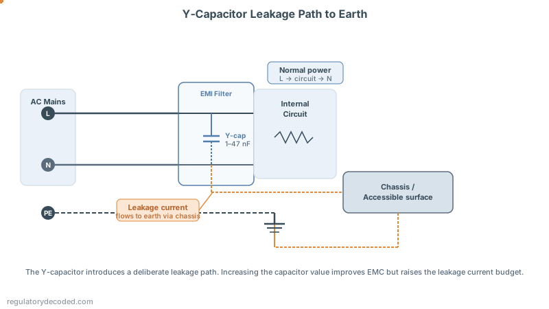
The second source is EMI Y-capacitors. Connected between the live conductors and the chassis to suppress high-frequency conducted noise, Y-capacitors (typically 1 to 47 nF) introduce a leakage path by design. This is a deliberate trade-off between EMC performance and the leakage current budget.
The third source is parasitic capacitance and inductance. Closely spaced conductive elements, such as a transformer primary winding running near a grounded core, form unintended reactive couplings. These drive displacement and induction currents into accessible parts even when the insulation is intact.
Certification standards including IEC 60990 and IEC 60601-1 set absolute leakage limits precisely because these effects cannot be designed away. Only their magnitude can be controlled.
Note: For how leakage current fits into the wider product risk evaluation, see the article on risk analysis as a compliance strategy.
How is leakage current calculated?
To predict leakage current, first calculate the total impedance of the leakage path. Impedance combines the resistive and reactive components into a single quantity that sets how much current flows for a given applied voltage.

The general impedance formula for an AC circuit is:
In most safety scenarios, insulation resistance R is very high and inductive reactance XL is small. The dominant term is capacitive reactance:
This has a direct consequence: as frequency rises, capacitive reactance falls and leakage current rises. A 10 nF Y-capacitor presents about 265 kΩ at 60 Hz but only 2.65 kΩ at 6 kHz. The leakage current at the higher frequency is 100 times greater for the same applied voltage.
Once total impedance is known, leakage current follows from Ohm’s Law for AC circuits:
Why frequency matters for physiological risk
At mains frequencies (50 or 60 Hz), the human body is highly susceptible to ventricular fibrillation. Currents on the order of a few tens of milliamps can disrupt cardiac rhythm within seconds.
Above roughly 1 kHz, the fibrillation threshold rises sharply. Cell membrane capacitance limits how fast ion channels respond to rapid stimulation. IEC 60479-1 reflects this by applying frequency-weighting factors to current limits above 100 Hz.
High-frequency leakage carries its own risks. It can heat deep tissue through resistive and dielectric losses, and it can interfere with active implanted medical devices such as pacemakers and cochlear implants.
The practical implication: leakage testing must cover the full frequency spectrum of a device’s operating voltages, not only the mains fundamental.
What are the six types of leakage current?
Six distinct types of leakage current appear in electrical equipment. They differ in physical cause, frequency content, and the design measures used to control them, so each needs to be understood separately. Total leakage is the vector sum of the individual components, not a simple arithmetic sum.
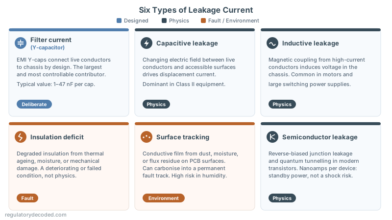
Filter current is by far the largest contributor in a well-designed product. Modern electronics need EMI filters to pass conducted emissions tests under CISPR 32, EN 55032, or equivalent. Those filters place Y-capacitors between the live lines and the chassis, giving a permanent, designed-in path for 50 or 60 Hz current to flow to earth.
Capacitive leakage often dominates in AC-powered equipment without a protective earth connection. Even with perfect insulation, the changing electric field across any capacitance between a live conductor and an accessible surface drives displacement current. Large metal areas near live wires and closely wound transformers are common sources.
Inductive leakage is less common in small electronics but prevalent in high-power industrial equipment. It occurs through magnetic coupling: a high-current wire near a conductive chassis induces a voltage in that chassis. Motors, large transformers, and high-frequency switching supplies are the frequent sources.
Insulation deficit leakage is fault-based rather than physics-based. Every dielectric has a finite insulation resistance that falls as the material ages, absorbs moisture, or sustains damage. Cracked wire jackets, degraded motor windings, and carbon-tracking across a PCB all fall here.
Surface tracking leakage occurs across the surface of an insulator rather than through it. Dust, moisture, and ionic contaminants such as solder flux residue form a conductive film that can produce a flashover or a carbonised track: a permanent, low-resistance fault. It is especially hazardous in humid or industrial environments.
Semiconductor leakage is a micro-scale effect from reverse-biased junctions and quantum tunnelling in modern transistors. Each transistor leaks nanoamps: a meaningful contributor to standby power rather than a direct shock hazard.
The table below summarises how these types differ in origin and character.
| Type | Primary cause | Deliberate? |
|---|---|---|
| Filter (Y-cap) | EMI suppression | Yes (design) |
| Capacitive | Electric field coupling | No (physics) |
| Inductive | Magnetic field coupling | No (physics) |
| Insulation deficit | Material degradation | No (fault) |
| Surface tracking | Contamination or moisture | No (environment) |
| Semiconductor | Junction physics | No (physics) |

Tip: When budgeting leakage during design, calculate the Y-capacitor contribution first. It is usually the largest and most controllable term. The EMC filter design article walks through the Y-capacitor sizing calculation and the emissions trade-off in detail. Reduce Y-capacitor values only after confirming that conducted emissions margins hold.
How does leakage current travel through a device?
Leakage current does not simply appear at an accessible surface. It propagates through the device structure via one or more coupling mechanisms before reaching the point where a user might touch it.
Conductive transfer occurs through a direct ohmic path: a degraded insulator, a metallic connection, or a protective earth conductor. Flowing through the protective earth under normal conditions, it registers as protective conductor current and the user does not feel it. An open or missing earth connection can redirect that current to accessible surfaces, where it becomes touch current.
The design and verification of protective earth systems is covered in the article on protective earth systems in product design.
Capacitive transfer dominates in well-insulated equipment. A changing electric field between a live conductor and a conductive surface drives a displacement current across the gap with no direct contact. This is the mechanism behind most touch current in Class I and Class II equipment.
Inductive transfer occurs through mutual inductance. A time-varying magnetic field from a current-carrying conductor induces a voltage in any nearby conductive loop. It is most relevant in equipment with large transformers or high-rate switching waveforms.
IEC 60990 defines three corresponding measurement categories. Touch current is measured through a simulated body impedance network between the accessible part and earth. Protective conductor current is measured with a low-value shunt in series with the earth connection. Patient leakage current (IEC 60601-1 only) is specific to medical equipment applied parts.
How dangerous is leakage current? Thresholds and physiological effects
Leakage current poses escalating hazards as its magnitude rises, from a barely perceptible tingle to ventricular fibrillation and cardiac arrest. IEC 60479-1 documents these physiological effects from experimental and epidemiological data. The IEC 60479-1 standard is the primary reference for the thresholds below.
The following thresholds apply to 50 or 60 Hz sinusoidal current with typical hand-to-foot contact. Values differ for other contact configurations, body masses, and current waveforms.

| Current (50/60 Hz) | Effect | What happens |
|---|---|---|
| 0.5 to 2 mA | Perceptible tingling | Mild discomfort. Can startle users and cause them to drop devices or lose balance. |
| 2 to 5 mA | Painful shock | Involuntary muscle contractions begin. The user retains grip but experiences significant pain. |
| 5 to 15 mA | Let-go failure | Sustained involuntary contraction prevents the user from releasing the device, extending exposure and increasing injury probability. |
| 15 to 30 mA | Respiratory paralysis | Chest muscle spasms inhibit breathing. Loss of consciousness is possible. |
| 30 mA and above | Ventricular fibrillation | Current at this level can disrupt the cardiac electrical cycle. Fibrillation can sustain itself without external intervention and is fatal without prompt treatment. |
The 30 mA figure at mains frequency is the physiological basis for the 30 mA trip current in residual current devices (RCDs), required by electrical installation standards in many jurisdictions.
These thresholds explain why touch current limits are set well below the let-go threshold. Product standards typically cap consumer equipment at 0.5 mA, an order of magnitude below the first pain threshold. IEC 60990 defines how that current is measured; the product standard sets the limit itself.
How does body impedance affect leakage current risk?
The severity of an exposure depends not only on current magnitude but on how that current distributes through the body. Body impedance sets that distribution, and it varies with contact path, skin condition, applied voltage, and frequency.
Skin impedance under dry conditions can reach tens of kilohms. Wet skin drops it to a few hundred ohms, raising body current by up to two orders of magnitude for the same applied voltage. Testing to worst-case wet contact is therefore essential for products used in kitchens, bathrooms, or outdoors.
Body impedance also falls as frequency rises. The reactive component of skin tissue, dominated by cell membrane capacitance, shunts higher-frequency currents more readily. This is one reason high-frequency leakage presents thermal risk even at amplitudes that would not electrocute at 50 Hz.
The human body impedance model in IEC 60990
IEC 60990 defines a hierarchy of body impedance models for leakage current measurement. The simplest is a single-resistor approximation. More realistic representations use RC networks that model the frequency-dependent behaviour of skin, muscle, and internal tissue.
This RC network behaves as a frequency-dependent low-pass filter. At 10 Hz, attenuation is negligible. Above 1 kHz, the reactive elements bypass the resistive branch, lowering effective impedance and letting more current pass for a given voltage.
Individual variability is substantial. Skin moisture, contact area, contact pressure, and body composition all affect impedance. Standards address this by specifying a reference body model rather than relying on individual measurements.
Note: The body impedance model in IEC 60990 is the basis for the measurement networks used in touch current testing. Part 2 of this series covers those circuits in detail, including the Figure 4 and Figure 5 networks from the standard.
What does IEC 60990 define, and how does it relate to product standards?
IEC 60990:2016, Methods of measurement of touch current and protective conductor current, is the foundational reference for leakage current terminology and measurement. Its definitions underpin the leakage requirements in virtually every product safety standard for mains-connected equipment, from IEC 62368-1 for audio/video and IT equipment to IEC 60335-1 for household appliances.
Touch current is the current that flows through a human body contacting one or more accessible parts. IEC 60990 quantifies it by passing the current through a specified body impedance network between the accessible part and a reference point. The network simulates the frequency-dependent impedance of the body and keeps results comparable across laboratories.
Protective conductor current is the current in the protective earth conductor under normal operating conditions, measured with a low-value shunt in series with the earth connection. If the earth connection breaks, it can divert to accessible surfaces and become a shock hazard.
IEC 60990 also harmonises test circuit configurations, instrument specifications, and reporting conditions. That makes a measurement in one laboratory reproducible in another: a core requirement for mutual recognition under international frameworks such as the IECEE CB Scheme.
Tip: IEC 60990 does not set pass/fail limits. Limits live in the applicable product standard. IEC 60990 defines how to measure; the product standard defines what is acceptable.
Five principles for designing and testing to leakage current limits
Effective leakage management needs both a design strategy and a systematic test plan. A well-designed product can still exceed limits under unexpected conditions, and a thorough test plan without upstream design controls produces results that are hard to improve retrospectively.
Preventive design: Minimise parasitic pathways through adequate creepage and clearance, insulation materials with stable dielectric properties across temperature and humidity, and an optimised EMI filter topology. Y-capacitor value is the primary design variable for filter current.
Comprehensive testing: Follow the IEC 60990 body model and measurement conditions. Test to worst case: maximum supply voltage, maximum frequency content, and wet contact where the use environment warrants it.
Risk-zone awareness: Even a few milliamps cause pain and let-go failure, and currents above 30 mA at mains frequency risk sudden death. Test limits are absolute maxima, not targets to approach.
Vulnerable user consideration: Children and some animals have lower body mass and potentially lower impedance than the adult reference model in IEC 60990. Products used where they may contact accessible parts may need more conservative leakage budgets than the standard minimum.
Frequency spectrum coverage: Validate leakage limits across the high-frequency content of the device’s switching waveforms. Thermal injury and implant interference can arise from high-frequency leakage even when mains-frequency limits are comfortably met.
Part 2 moves from theory to practice with standardised test networks, IEC 62353 methods, and instrumentation selection. Part 3 addresses PCB design, EMI filter selection, insulation qualification, and IEC 60664 validation.
Frequently asked questions about leakage current
The questions below cover what engineers most often search when scoping a leakage current problem.
What is leakage current in simple terms?
Leakage current is the small current that flows outside the intended circuit path, typically from a live conductor to earth or to an accessible surface. It exists in every mains-connected product through insulation, EMI filter capacitors, and parasitic coupling, and safety standards cap how much is allowed.
What is an acceptable leakage current limit?
It depends on the product standard, not on IEC 60990. Consumer equipment is commonly limited to 0.5 mA touch current, while corded and permanently connected equipment may be allowed more under specific conditions. Always read the limit from the standard that applies to your product category.
What is the difference between leakage current and touch current?
Leakage current is the general term for unintended current flow. Touch current is the specific portion that would pass through a person contacting an accessible part, measured through a body impedance network. Protective conductor current is the portion returning through the earth conductor.
What causes high leakage current in a power supply?
The dominant cause is usually the EMI filter Y-capacitors, which connect the mains to earth by design. Transformer interwinding capacitance, PCB parasitics, and degraded insulation add to the total. Oversized Y-capacitors are the most common reason a product exceeds its limit.
Is leakage current dangerous?
Within standard limits it is not. Above them it can cause pain, prevent a user from letting go, and at a few tens of milliamps trigger ventricular fibrillation. This is why limits sit an order of magnitude below the first pain threshold. If you are researching this after a shock incident, seek medical assessment: survivable shocks can carry delayed cardiac risk.
Conclusion
Leakage current is unavoidable, so the engineering goal is to quantify and minimise it, with the Y-capacitor contribution as the largest controllable term. The physiological thresholds in IEC 60479-1 explain why product standards cap consumer touch current an order of magnitude below the first pain threshold. IEC 60990 defines how to measure; the applicable product standard sets the limit you must meet.
With the theory established, the next step is measurement: Part 2 shows how to build the test setup and read the result correctly.
References and further reading
Standards
- IEC 60990:2016, Methods of measurement of touch current and protective conductor current
- IEC 60479-1:2018, Effects of current on human beings and livestock, Part 1: General aspects
- IEC 60479-2:2019, Effects of current on human beings and livestock, Part 2: Special aspects
Foundational research on electrical shock thresholds
- [1] Dalziel, C.F. & Ogden, E. (1943). Effect of frequency on let-go currents. Electrical Engineering, December 1943. Semantic Scholar — Original human-subject experiments establishing the 5–15 mA let-go zone.
- Dalziel, C.F. & Lee, W.R. (1968). Reevaluation of lethal electric currents. IEEE Transactions on Industry and General Applications, 5, 467–476. IEEE Xplore — Established the 9 mA (men) and 6 mA (women) 99.5th-percentile let-go thresholds; still cited by IEC 60479-1.
- [2] Biegelmeier, G. & Lee, W.R. (1980). New considerations on the threshold of ventricular fibrillation for AC shocks at 50–60 Hz. IEE Proceedings A, 127(2), 103–110. IET Digital Library — The foundational VF threshold curve underpinning IEC 60479-2 and the 30 mA safety limit.
- Krasteva, V. et al. (2021). Ventricular fibrillation threshold vs alternating current shock duration. IEEE EMC + SIPI 2021. PubMed — Modern validation of the Biegelmeier curve.
Electrophysiology and cardiac effects of electric shock
- Lerman, B.B. et al. (2023). The electrophysiology of electrocution. Heart Rhythm O2. PMC open access — Comprehensive review of the cardiac mechanism of electrocution. From Johns Hopkins.
- Waldmann, V. et al. (2017). Mortality and risk of cardiac complications among immediate survivors of accidental electric shock. PMC open access — Epidemiological evidence that survivable shocks carry elevated long-term cardiac risk.
Human body impedance
- Ackmann, J.J. & Seitz, M.A. (1984). Frequency dispersions of human skin dielectrics. Biophysical Journal, 45, 767–771. PMC open access — Classic experimental data on skin resistance and capacitance vs. frequency; the basis for the Cole-Cole model in IEC 60990.
- [4] Patel, N. et al. (2021). Estimation of skin impedance models with experimental data. PMC open access — Updated validation of skin impedance models.
- [3] Reilly, J.P. (1998). Applied Bioelectricity: From Electrical Stimulation to Electropathology. Springer. Springer — Standard reference for frequency-weighted current thresholds above 1 kHz.
EMI filter design and leakage current trade-off
- Bai, H. et al. (2016). Conducted EMI mitigation schemes in isolated switching-mode power supply without the need of a Y-capacitor. IEEE Transactions on Power Electronics, 32(4), 2687–2703. IEEE Xplore — Addresses the EMC-vs-leakage trade-off of Y-capacitors.
Technical articles
- Electric shock stimulation for complex leakage current waveforms — In Compliance Magazine
- Physiological effects of electricity — All About Circuits
- Electric hazards and the human body — MSU OpenBooks