Most creepage and clearance distances get calculated once, early, by one engineer reading one table. The number then travels through the rest of the project as though it were settled.
It is not settled. The same design needs different distances when the installation position changes, when the product ships to a market at altitude, and again when two individually compliant boards are bolted into one enclosure.
This article walks the variables that move the number after you think you have it, and shows where the calculation stops being a lookup and starts being a review.
Do you use RMS or peak voltage to determine creepage and clearance distances?
The first variable is the one people skip, because it looks obvious. Working voltage is not a single number, and creepage and clearance do not use the same one.
Clearance is an air breakdown problem. Air fails on peak voltage, so clearance follows the peak working voltage and, where mains transients reach the circuit, the rated impulse voltage.
Creepage is a surface tracking problem. Tracking is a slow electrochemical process driven by the sustained stress on the surface, so creepage follows the RMS working voltage.
Where this goes wrong
Switch-mode power supplies are where the two diverge sharply. A primary side switching node sits at a recurring peak far above the mains peak, while its RMS value stays modest.
Take the peak for creepage and you oversize the layout. Take the RMS for clearance and you undersize the insulation, which is the failure that matters.
Neither error announces itself during design. Both surface at the dielectric strength test, where an undersized gap is one of the most common causes of a hipot test failure.
One boundary is worth naming here and then leaving alone. Above 30 kHz, IEC 60664-1 stops being the right document and IEC 60664-4 governs insulation coordination instead. If your working voltage is a high-frequency waveform, you are reading the wrong standard.
Which overvoltage category applies to your product?
Overvoltage category describes the installation, not the product. It answers one question: how large a transient can arrive at the terminals from the supply system?
That depends on electrical distance from the origin of the installation. Equipment plugged into a socket downstream of a building’s distribution sits further from the origin than equipment wired permanently into a fixed installation.
The two common errors
Engineers reach for the category they have used before, on a product that sat somewhere else in the installation. Permanently connected industrial equipment gets dimensioned as though it were a plug-connected appliance, and the transient assumption is wrong from the first line.
The second error is missing a legitimate reduction. A transformer, a surge protective device, or an impedance deliberately placed between the supply and the circuit can reduce the transient that reaches it.
Moving down one category lowers the rated impulse voltage the design must withstand, which shortens clearance. Moving up one category lengthens it. The category is a design input you can sometimes influence, not a fixed property of the product.
Is your pollution degree the room or the inside of the enclosure?
Pollution degree is a property of the micro-environment immediately around the insulation, not the room the product lives in. This distinction changes creepage and leaves clearance untouched.
A sealed enclosure in a dirty factory can hold a cleaner micro-environment than the room implies. A vented, fan-cooled enclosure in a clean office pulls the room’s dust across the board continuously. A micro-environment is dirtier than the room implies.
What does not count as protection
Two assumptions fail regularly, and both are worth checking before the layout is frozen.
- Solder mask is not a protective coating. It is a soldering process aid, and it does not by itself move a board to a lower pollution degree.
- A conformal coating only changes the pollution degree when it meets the coating requirements of IEC 60664-3. It covers coverage, adhesion and process control, not simply the presence of a film.
Both are reviewable at design stage and expensive to discover at certification.
Where does the material group actually come from?
Material group is set by the comparative tracking index of the insulating material. It affects creepage only, never clearance, because clearance is an air property and the substrate is irrelevant to it.
The number belongs to the laminate you are buying, and it appears on the laminate datasheet. It does not belong to “FR-4” as a category, because FR-4 is a specification family that spans several tracking performances.
A design assumed to sit in a better material group than the purchased laminate delivers is non-compliant on paper the day the first board arrives. This is a purchasing question as much as a design one, and it is worth pinning in the bill of materials.
Does altitude affect creepage, or only clearance?
This is the most misapplied variable in the set, and the answer is asymmetric.
Air gets thinner with altitude, so its dielectric strength falls and clearance must grow. Above a reference altitude of 2,000 metres, IEC 60664-1 applies a correction factor greater than one to clearance.
Creepage does not get corrected. Surface tracking is an electrochemical process on a solid surface, and it does not depend on air density in the same way. Applying an altitude factor to creepage is a common and unnecessary oversizing.
Why this bites harder than it looks
The correction is not trivial. At altitudes around 3,000 metres it adds somewhere between a quarter and a third to the clearance figure. Treat that as illustrative and confirm the factor against the current edition of IEC 60664-1 [VERIFY].
A third more clearance is often the difference between a distance the chosen connector pitch can hold and one it cannot. The variable is applied late, after the mechanical design is committed, which is why it surfaces as a redesign rather than a calculation.
Altitude also travels with the market, not the factory. A product designed and tested at sea level and then sold into Bogotá, Mexico City, Denver or a mountain plant is the same product facing a different requirement.
What happens when two compliant boards are assembled?
Here is the failure your CAD tool cannot see. Design rule checking runs per board. It dimensions the paths inside one board outline and reports the board as compliant, which it is.
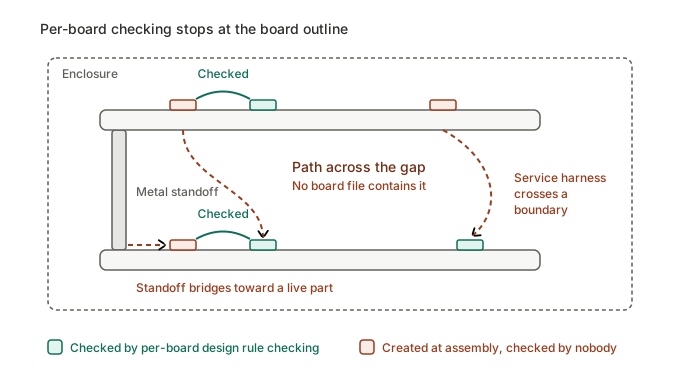
The product is not one board. It is two or more boards, an enclosure, a harness, and the hardware holding them together.
The paths nobody dimensioned
Assembly creates paths that exist in no board file, and these are the ones found late.
- Two stacked boards, each internally compliant, present a new path across the gap between them that neither DRC evaluated.
- A metal standoff or fixing screw bridges toward a live part and shortens a path that was adequate in the board file.
- A harness routed for serviceability lies across a boundary the layout engineer treated as clear air.
- A connector on the mating board brings a different net into proximity with a track that had no neighbour when it was checked.
None of these are layout mistakes. Each board is correct. The assembly is what fails, which is why the problem survives every board-level review and reaches the test house intact.
The same blind spot applies to components deliberately bridging the barrier. A Y-capacitor across primary and secondary sits on the insulation boundary, and its footprint and lead dress belong to the leakage current design decisions as much as to the spacing calculation.
Why it is found late
The assembly path only becomes visible when a real unit exists, and by then the mechanical design is fixed. The tooling may be already committed. The fix at that point is a spacer, a barrier, a rerouted harness or a new enclosure. None of those are cheap.
This is a review question rather than a calculation question. It needs someone looking at the assembled product against the insulation requirements, not another pass through the board file.
The clearance rule in your CAD tool is not a safety rule
One further trap sits inside the tooling itself. The clearance constraint in a PCB design tool is a manufacturing rule. It exists to keep the fabricator’s process within tolerance, and it is set from the board house capability. It’s not from an insulation coordination requirement.
A board that passes DRC has satisfied the fabricator. It has not been shown to satisfy the safety requirement, and the two numbers have no relationship to each other beyond the coincidence of sharing a name.
Where the safety distance is larger, the layout engineer has to enter it deliberately as a separate constraint, net class by net class. Where nobody does that, the board is dimensioned to the fabricator’s minimum and everyone downstream assumes it was dimensioned to the standard.
Why do DC and PV systems at 1,000 to 1,500 V behave differently?
Direct current changes the physics of the surface problem. Alternating voltage crosses zero twice per cycle, which interrupts the electrochemical process that drives tracking. Direct voltage never does.
Under a DC field with moisture and contamination present, ion migration proceeds continuously in one direction. Tracking and metal migration behave differently from the AC case that the familiar tables were built around.
The practical consequence is that a DC design cannot borrow an AC intuition about how much margin a given surface offers. Contamination that a mains circuit tolerates for years can produce a conductive bridge on a DC circuit at a similar voltage, because nothing interrupts the process.
The transient question
The second difference is where the transient comes from. It is the point most often carried over wrongly from AC design.
An overvoltage category expresses the transient arriving from a mains supply system. A photovoltaic string or a battery bank is not fed from that system, so the mains transient assumption does not automatically apply.
The design has to identify its own transient sources instead: switching events, lightning coupling into the array, and disturbances arriving from the inverter side.
Carrying an AC overvoltage category across to a DC architecture, without asking where the transient actually originates, produces a number that looks defensible on paper and is wrong in the field.
Where altitude and DC compound
Utility scale solar and storage sit at altitude more often than most equipment categories, because that is where the irradiance is. A 1,500 V DC string at 3,000 metres carries both a large base clearance and the altitude correction on top of it.
For photovoltaic equipment specifically, confirm which requirements come from IEC 60664-1 and which come from the IEC 62109 series, because the split is not always where designers assume it is [VERIFY].
How do these variables compound on a single design?
Taken one at a time, each variable looks like a modest adjustment. Designs do not meet them one at a time.
Consider one board that clears its requirements comfortably at the design assumptions: sea level, a clean sealed enclosure, a plug-connected installation position, and a laminate assumed to sit in a good material group.
Now change four assumptions that a sales decision can change without any engineering input at all.
- The product is sold into a market at 3,000 metres, so clearance takes the altitude correction.
- It is installed permanently rather than plug-connected, moving it up an overvoltage category and raising the impulse voltage the clearance must withstand.
- The enclosure specified for that market is vented, moving the micro-environment to a dirtier pollution degree and lengthening creepage.
- The purchased laminate turns out to sit a material group below the assumption, lengthening creepage again.
Two of those changes push clearance out and two push creepage out, and they act on the same physical geometry at the same time. The comfortable margin is gone, and no single decision on the list was unreasonable.
There is one rule that catches the tail of this. Where the computed creepage falls below the clearance, creepage must be raised to at least the clearance value. The two are not independent, and the larger requirement governs.
Reinforced insulation compounds it further, and not symmetrically. Reinforced creepage is twice the basic value, while reinforced clearance steps up to the next higher rated impulse voltage rather than doubling.
Engineers who double both are oversizing one and, depending on where the impulse steps fall, potentially undersizing the other. Confirm the rule against the current edition of IEC 60664-1 before you commit a layout to it.
Conclusion
Creepage and clearance are not one calculation but a chain of inputs, and every input in that chain can change after the layout is frozen. Altitude corrects clearance and leaves creepage alone, which is the asymmetry most often applied backwards.
The path that fails is usually the one no board file contains, because it only exists once the product is assembled.
If your distances were dimensioned per board and never re-examined against the finished assembly, that is the review worth doing before the test house does it for you.